AREUCD
(Automated Reverse
Engineering of Use Case Diagrams)
Tool support is essential for the effective application of the REUCD
process. For a highly complex software system, the corresponding use case model
may contain up to four hundred use cases. Use cases are not sorted in any
chronological order. Relationships linking the use cases with other use cases
and actors also not sorted in any fashion either. Therefore, performing the
REUCD process for such system manually is a very cumbersome task that is prone
to many inconsistencies. Even for a relatively smaller use case model, one that
contains twenty use cases, the application of the REUCD process is still
vulnerable to mistakes.
In this paper, we feature the tool AREUCD (Automated REUCD), which supports
the two way generation of use case diagrams from use case descriptions and vice
versa. In order to generate use case diagrams from use case descriptions,
AREUCD is loaded with a UC description file (‘.ucd’
extension). AREUCD parses through the descriptions of all the given use case
descriptions and actors and generates a file containing the corresponding use
case diagram. The use case diagram is generated in XML format, which will allow
it to be displayable by UML modeling tools. Conversely, in order to generate
use case description ‘skeletons’, AREUCD is loaded with UC diagram
file. The UC diagram can be generated by a UML modeling tool. The UC diagram
must be in XML format, however this is not an issue
since almost all UML modeling tools store information about their models in XML
format. Upon parsing the diagram or description files, the properties of the
given UC descriptions or diagram is displayed (see Figure 2). Figure 1 shows an overview of the
operation of AREUCD.
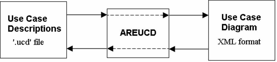
Fig. 1 An overview of AREUCD
Given the UC descriptions file for an Online Hockey Store system, AREUCD can automatically generate the corresponding UC diagram (see Figure 2).
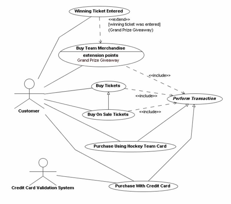
Fig. 1 The generated UC
diagram for the online hockey store system using AREUCD.
AREUCD can also be used to generate Activity diagrams from UC descriptions that are described in the SUCD format. Every type of flow inside a use case can be modeled by a separate activity diagram (see Fig. 3). In fact, workflows can span several UCs. All these relations can be modeled by AREUCD as well.
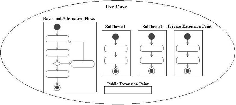
Fig
3. Different type of flows
inside a UC
AREUCD is a primitive tool. A very early release (still unstable though) of AREUCD can be downloaded here.